Now that I have a few amp builds and repairs under my belt, I have decided my next amp project will be a Dumble ODS clone. I’ve always loved the recorded Dumble tones, and whether or not it’s apocryphal, the story is that Dumble was trying to replicate the tone of an overdriven Super Reverb when he set out to build the first ODS. Considering the Super Reverb is my all-time favorite amp, all the more reason to add an ODS clone to the collection. Specifically, I’ve decided to build ODS #102, simply because it’s an amp owned by Robben Ford, and he has one of the quintessential Dumble tones.
Before actually building the amp, I wanted to take a look at the circuit and figure out what makes it tick. The early ODS amps were likely built from or based on black panel Fender Twin Reverbs. The 4x6L6 output, the solid state rectifier, and the transformers of the early models were all very similar to the Twin Reverb. And since I am intimately familiar with the AB763 Fender circuit having built 2 and repaired others, I think the AB763 Twin Reverb is a great frame of reference for comparison to the ODS.
Twin Reverb vs. ODS Input Stage
The Twin Reverb has two channels, with two inputs. But the two channels have identical input gain stages, and the two inputs per channel feed a single common cathode gain stage, so there really is only one circuit to consider.
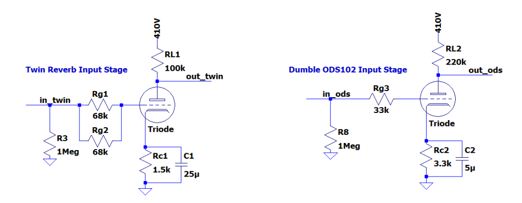
The Dumble ODS has a single channel with two inputs–Normal and FET. More on the FET input later. Assuming plugging into the #1 input of the Twin Reverb and the Normal input of the ODS, the circuits are as follows:

Topologically, the two input stages are nearly identical. When plugging into input 1 of the Twin Reverb, you see Rg1 and Rg2 in parallel, resulting in a grid resistor of 34k, practically identical to grid resistor of the ODS. The load and cathode resistors are both larger for the ODS, resulting in less DC current and higher gain in the ODS. But both cathode resistors are bypassed with large capacitors, so both should be pretty high gain.
The bypass capacitor and cathode resistors in parallel create a high pass filter that can theoretically impact the bass response. The RC for the Twin rolls off at 4Hz, the RC for the ODS rolls off at 9Hz. Functionally, both amps’ input stages have a low frequency roll off well below the range of human hearing, let alone what a guitar can provide.

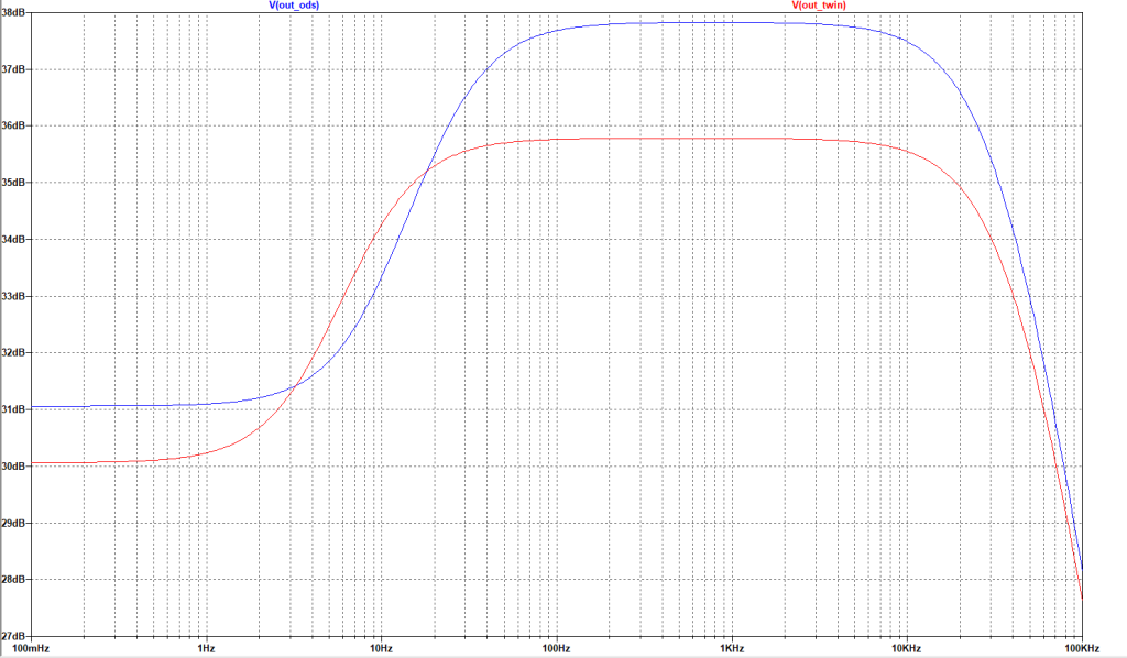
The above plot is the simulation result of the gains magnitudes across frequency (Vout/Vin) of the input stages of the Twin (red) and ODS (blue). As expected, the Twin has a slightly lower frequency bass rolloff, both amps have high mid band gain, but the ODS’s gain is slightly higher (~38dB vs. 36dB).
ODS FET Input
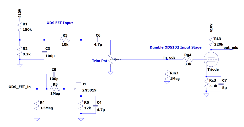
The ODS has a second input, called the FET input. This is not a second channel in the way that the Vibrato and Normal channels are two different signal paths in a Twin, rather the FET input places a JFET-based common source amplifier between the guitar and the common cathode amplifier, which you’d normally drive directly, like so:

R1, R2, and C3 form a lower voltage rail off the high voltage power supply, R3 is the load resistor, R6 and C4 are the source resistor for biasing and the bypass capacitor for high gain. C6 is the AC coupling cap, and the Trim Pot is used as a resistor divider to trim out some of the added gain.
I used a generic 2N3819 N-channel JFET in simulation, because I had the model for it handy. Depending on the particular JFET choice, the circuit can have up to 20dB of mid band gain pre-trim.

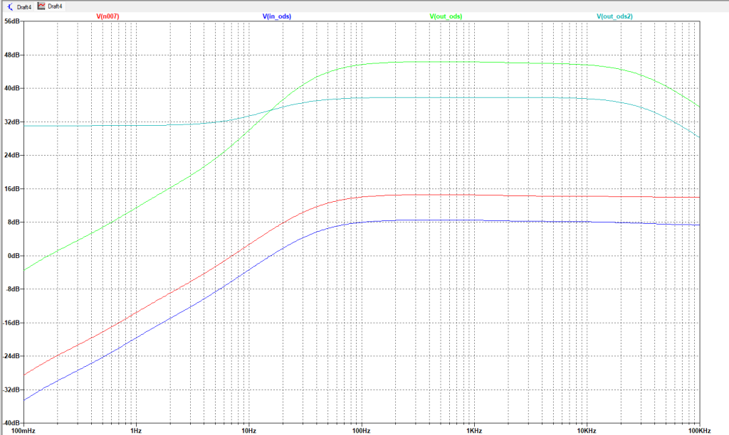
The above sim results are the gain magnitude of the JFET stage pre-trimming (red), post-trimming (dark blue), output gain of the tube common cathode stage when driven by the FET stage (green), and for reference, the same magnitude plot from above of the commong cathode stage driven directly (light blue).
The FET stage alone provides about 16 dB of gain midband, and because I have the trim pot set to divide the output signal in half, about 10 dB of gain post trim. Notably, it has a bass roll off between 10-100Hz, comparable to the tube stage, but does not roll off any treble at all.
When stacked with the common cathode gain stage and compared to the standalone common cathode gain stage, the JFET input has more mid band gain and a more exaggerated low end roll off. Because of the way it’s biased, I also expect it to have plenty of headroom. My guess is, this circuit will cut some bass and sound brighter, and depending on how the trimmer is set, could provide a substantial boost, as if you were using a clean boost pedal in front of the amp.
Conclusion
So, into the ODS normal input, the input stage looks very much like a conventional, Fender-style input gain stage. But the FET input adds a significant departure from the 60s-era Fenders.
For the next build log, I plan to do a circuit analysis of the tone stack and following gain stages, where I expect I will see the ODS significantly split from vintage Fenders.

